Friday, April 23, 2010

Octave Mandolin Build, Part 8

Gluing the Headstock/Peghead Veneer
Kawalek's kit came with veneer for the top of the headstock, but I found a piece of cherry at the the local speciality woods store that had a nice 'flame' to it and decided to use it for both the front and back of my headstock. I cut off a length of the cherry long enough to cover the peghead. I then resawed it to about 8mm thickness, and stuck it under the planer until I had a thickness of about 5mm. I also had to take a little off of the back of the peghead itself to get the overall thickness (once both pieces of the veneer were glued on) to the proper dimensions. Here are some pics.

In this one you can see that both pieces of veneer (which have been dry clamped) are still too thick, as the tuning machines won't be able to work.


Getting closer . . .


And, finally . . .


Once I got to this point I stopped planing, as I knew that there would be some sanding to take an additional 1-2 mm off the veneer. I then drilled two 1/16" holes in the veneer to hold it in place with brad nails after I got it glued up, but before I could clamp it. I also marked on the veneer which piece was for the top and which was for the bottom of the peghead. I then marked out the size of the truss rod slot on the top piece of veneer so that I would know where to cut and chisel it out. Here are some pics:

Notice in this picture I have the nut inserted for two reasons: 1) so I know exactly where the veneer needs to be; and, 2) so that I can angle the piece of veneer, by sanding it, to sit flush against the nut once it is glued in.


And here it is all clamped up. Be sure to use a couple of additional pieces of wood to help in the clamping. That's all there is to it.

Wednesday, April 14, 2010

Octave Mandolin Build, Part 7

Cutting the Binding Channels and Installing the Bindings
Before I routed the top and back binding channels, I coated the edges with clear shellac in order to minimize tear-out. There are numerous opinions out there concerning whether this step is or is not necessary. But, because I am insanely anal retentive about certain things, I went ahead and shellaced just to be sure.


Depending on how wide and how thick your binding is will dictate the depth and width of the channel you route. When routing, it is usually best to take two or three passes (changing depth and width after each), rather than trying to route the entire channel depth/width all in one pass. The picture below shows one route, and then the second one started. Hopefully the picture is self-explanitory.


Here is the back fully routed.


Once the route is complete you can apply the binding. Since my binding is made out of ABS I used CA glue on the back (on the soundboard I used Titebond wood glue . . . as a test). It is a good idea to get everything set-up and ready to go before you start gluing. So, you will want to make sure that the binding channel is completely clean and level. If it is not then you can chisel out the areas that need work. You also want to have a number of pieces of tape cut and ready to go (see the pics below) to 'clamp' the binding once glued. Starting at the neck block, place a little glue in the channel, fit the binding, and get a couple of pieces of tape on it (place the tape on the back and/or soundboard first and then pull it tightly over the edge, securing it on the side). As you progress try to lap each consecutive piece of tape over the previous one to aid in the tape's holding power. Here are a couple of pictures:


Be sure to give the glue adequate time to try before you remove the tape. After you do take the tape off, you will then need to scrape and sand the binding. I used hand scrapers to remove the majority of the excess binding and then sanded the rest. Here is the back after those steps were taken:


Here are some pictures of the binding of the soundboard:


One of the things that I should have done was shellac the top a little more. As you can see from the picture below, when I took the tape off some of the fine fibers from the soundboard, where it was not shellaced, came off with the tape.


Here is the soundboard and back binding completed (N.B., if you were worried about adding the shellac, don't. The single coat very easily sands off).


Tuesday, April 13, 2010

Forms, Patterns and Helpful Tools, Part 3

Router Table Jig for the Binding Ledge
One of the things I've had a lot of trouble with in the past is routing the binding ledge. It can be (and still is . . . at least for me!) pretty tricky and a little more than nerve racking. When I built an Irish bouzouki a couple of years ago I used a flush-cut (aka, flush trim) bit with a couple of bearings that were just a skosh smaller than the actual bit diameter. I also free-handed the channel. Well, long story short, I blew out part of the side. I've experimented with other methods since. I would like to buy one of those nice routing jigs from Stew-Mac or Luthier's Merc but I don't have the cash right now. Thanks to the helpful folks on Mandolin Cafe I was directed to Lynn Dudenbostel's site (documenting a build for, no less than, Chris Thile!), and Stan Miller's webpage. On each I saw their set-ups for routing bindings. I decided to try and construct something similar. So, here goes . . .

First, I cut a piece of 1"x4" pine a few inches strong of the actual length that I needed (just measure your router table to find this length). Next, using a keyhole bit I routed a channel in the center of the 1"x4" large enough to insert a couple of hex head bolts. I made one complete pass, and then moved the router table fence about 1/8" and made another pass. Again, this was done to be able to slide the hex head bolts in the channel . . . that is why it looks a hair off center. Here is a picture:


Next, I cut another piece of 1"x4" about half the lenght of the first, marked a centerline, and drilled two holes to accept the bolts.


Then, on the bottom side of the top piece, using a straight router bit (if you are unfamiliar with router bits, here is a basic, but good tutorial), I cut a channel about 2" long. When that was complete, I cut the angles on the top and bottom pieces, sanded them smooth, and added a washer and wing nut each to the bolts. I also drilled a hole in the channel on the bottom piece about 3/4" in from the end to accept the router table bit when cutting the binding channel. Here are a few pics:


Clamp it down, and you are good to go:


When you use this set-up, the sides of the box simply ride along the lower piece of pine. The top piece of pine is used to set the thickness of cut. By moving the router up and/or down in the table you can control the depth of cut. I've found that one of the keys to making this work properly is to hold the back of the box being routed (the part of the mandolin closest to your belly while standing at the table) at a slight angle down from the bit. In other words, the box should slope downwards from the router bit to you. If you raise the back of the box you will cut too far into the back and/or soundboard. Overall, with a little practice this seems to work like a charm. I'm still a long, long way from getting my binding routes 'perfect' . . . but is there really such a thing in this life anyway? :) I hope this is helpful.

Octave Mandolin Build, Part 6

Fitting, Gluing and Flush Routing the Soundboard
Like the back, I re-marked the center lines on the soundboard and then lightly dry clamped it to the neck and tail blocks.


I then marked where the braces and tone bars needed to be cut, as well as their positions on the sides, which I transfered to the kerf.


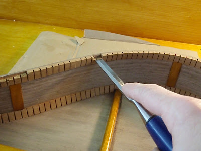
When everything was marked I then cut and chiseled the braces, tone bars and kerf.


Once everything was ready to go, I put a bead of glue on the kerf  (N.B., try not to spread too much, as you won't have a chance to wipe away any squeeze-out from the inside of the box). When the glue is adequately spread about, you can clamp the soundboard.


When the glue dried (I let it sit overnight before unclamping), I routed off the excess with a flush-cut bit as I did with the back.


Here is the box after I routed the overhang:


Sunday, April 11, 2010

Octave Mandolin Build, Part 5

Sanding the Sides and Kerf
After the kerf dried I placed the sides back into the mando form, and then mounted the form 'into' the sanding jig. Using chalk, I marked the sides along with the neck and tail blocks before sanding. While sanding you can check often to see when the sides and kerf level up (i.e., when the chalk disappears). When the top was completed I flipped it over and sanded the back following the same method. Here are some pics:


Gluing and Flush Routing the Back
In order to glue on the back I: 1) re-marked centerlines on the neck and tail blocks; 2) laid the back down and placed the sides on it (holding it in place w/two clamps), and lining up the centerline on the back with the centerlines on the neck and tail blocks; 3) marked the where the braces hung outside of the sides, and marked where the kerf would be cut out to accept the shortened braces; 4) cut the braces to size; 5) cut out the kerf using a pull saw and chisel; 6) glued the back sides; and, 7) placed the back on the sides and clamped it up. I didn't take a lot of pictures of the entire process for the back, but I did when fitting and gluing the soundboard, so there will be a number of pictures for that step, all of which pretty much correspond to the back.

Getting everything set-up and ready to go:


The water marks in the pic below are from a damp rag I used to wipe up excess glue. The glue in the slots of the kerf should not be wiped clean. It will, however, dry clear, so you don't have to worry about it. Just try to clean the stuff that squirts outside of the kerf and onto the back or soundboard (depending on which you choose to glue on first).


When I unclamped it I decided that I wanted the braces and center to be darker, so I masked everything off and gave it about 8-10 more coats of shellac.


I then, using a flush cut bit on the router table, removed the excess overhang from the back.


The final back and sides look like this:


In the next entry we will talk about fitting and gluing the soundboard.